date: 2024-01-16
title: Logic-Circuits]"
status: DONE
author:
  - AllenYGY
tags:
  - Boolean-Algebra
  - DNF&CNF
  - DiscreteStructure
  - Lec15
  - NOTE
created: 2024-01-16T21:03
updated: 2024-04-08T19:49
publish: True
Logic-Circuits]"
Logic Circuits
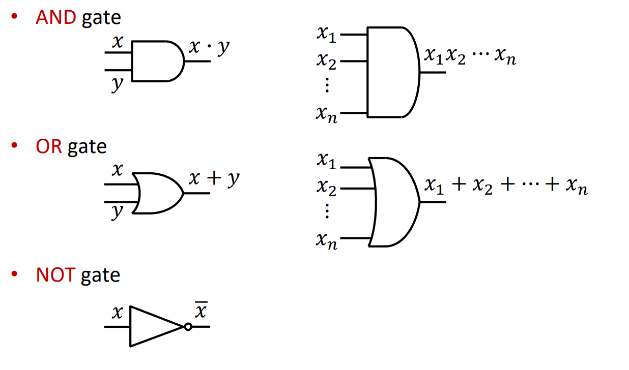
- Logic gate symbols
- Logic circuits design
- Minimization of logic circuits
Logic Gates
*
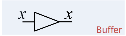
- Buffer
- It is used for delay
- Useful for timing purpose
- Not for the logical purpose
Logic Circuit
- Steps in Design of Logical Circuits (Without minimization)
- Find the inputs and outputs
- Inputs: number of variables in the Boolean function
- Outputs: how many functions are required
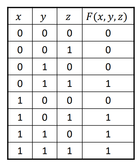
- Draw the truth table
- Truth table: indicate the relationship between outputs and inputs
- Specify what ‘0’ and ‘1’ (in input and output) in the table represent?
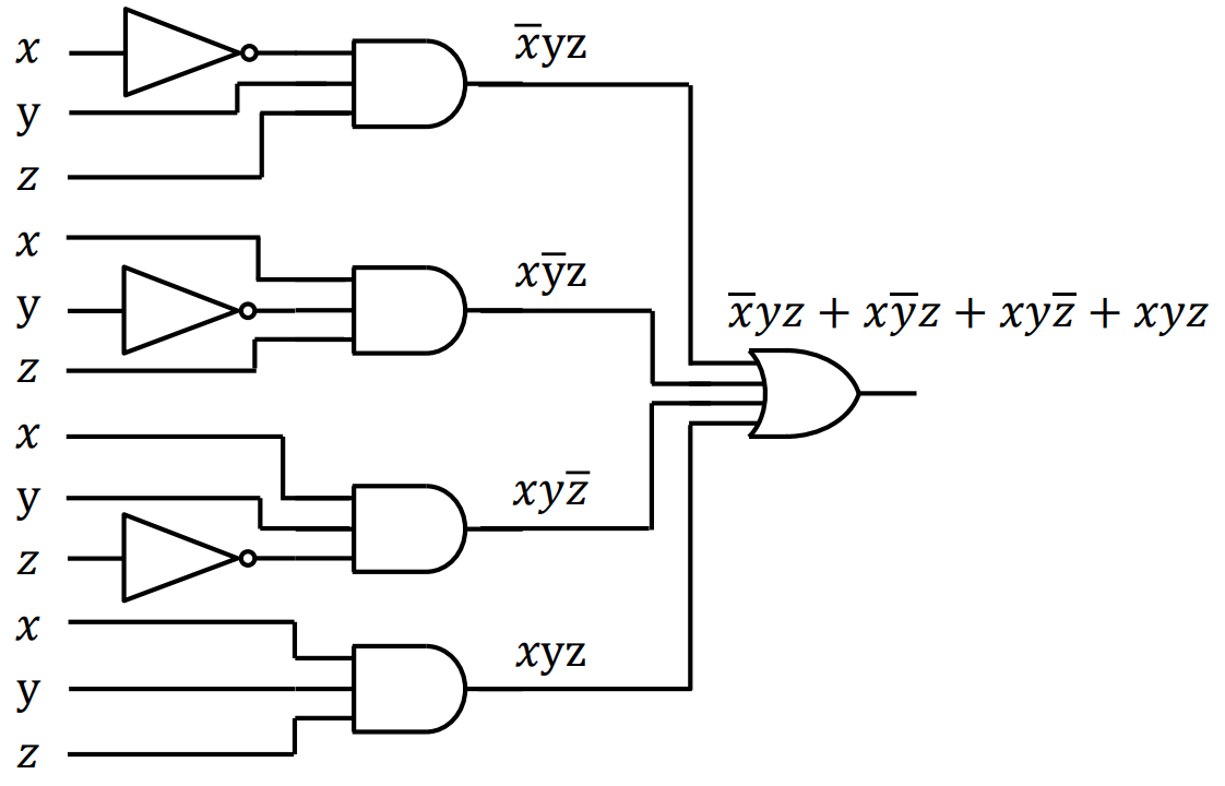
- Figure out the functions
- Use sum of products or product of sums
- Design the logical circuits
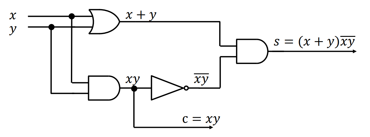
Logic Circuits – Half Adder
- Add two bits
- 0 + 0 = 0
- 0 + 1 = 1
- 1 + 0 = 1
- 1 + 1 = 0 and carry 1 to the next place
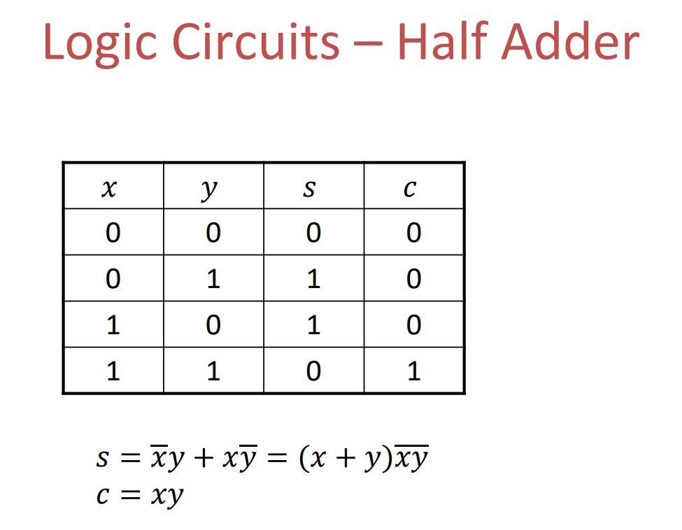
- S: 本位
- C: 进位
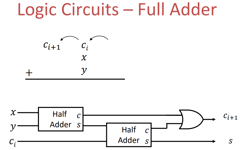
Logic Circuit - Full Adder
Steps in Design of Logical Circuits(With Minimization)
- Find the inputs and outputs
- Inputs: number of variables in the Boolean function
- Outputs: how many functions are required
- Draw the truth table
- Truth table: indicate the relationship between outputs and inputs
- Specify what ‘0’ and ‘1’ (in input and output) in the table represent?
- Figure out the functions
- Use sum of products or product of sums
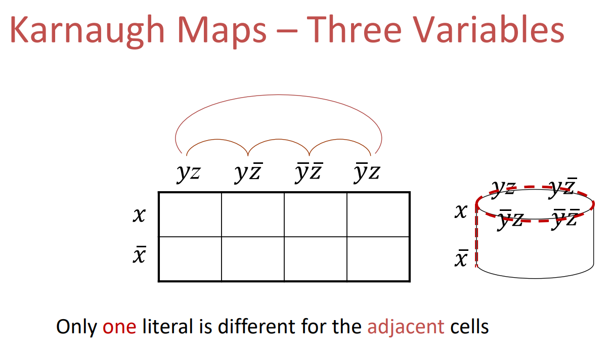
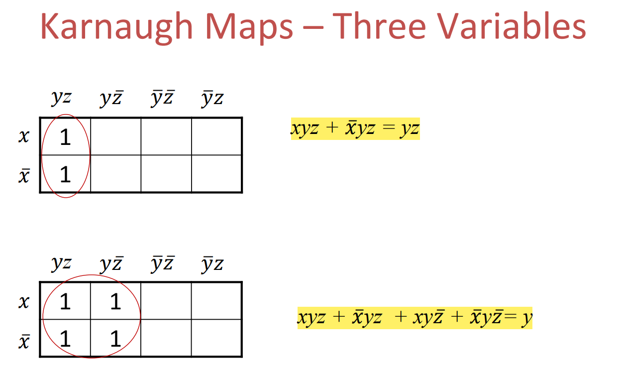
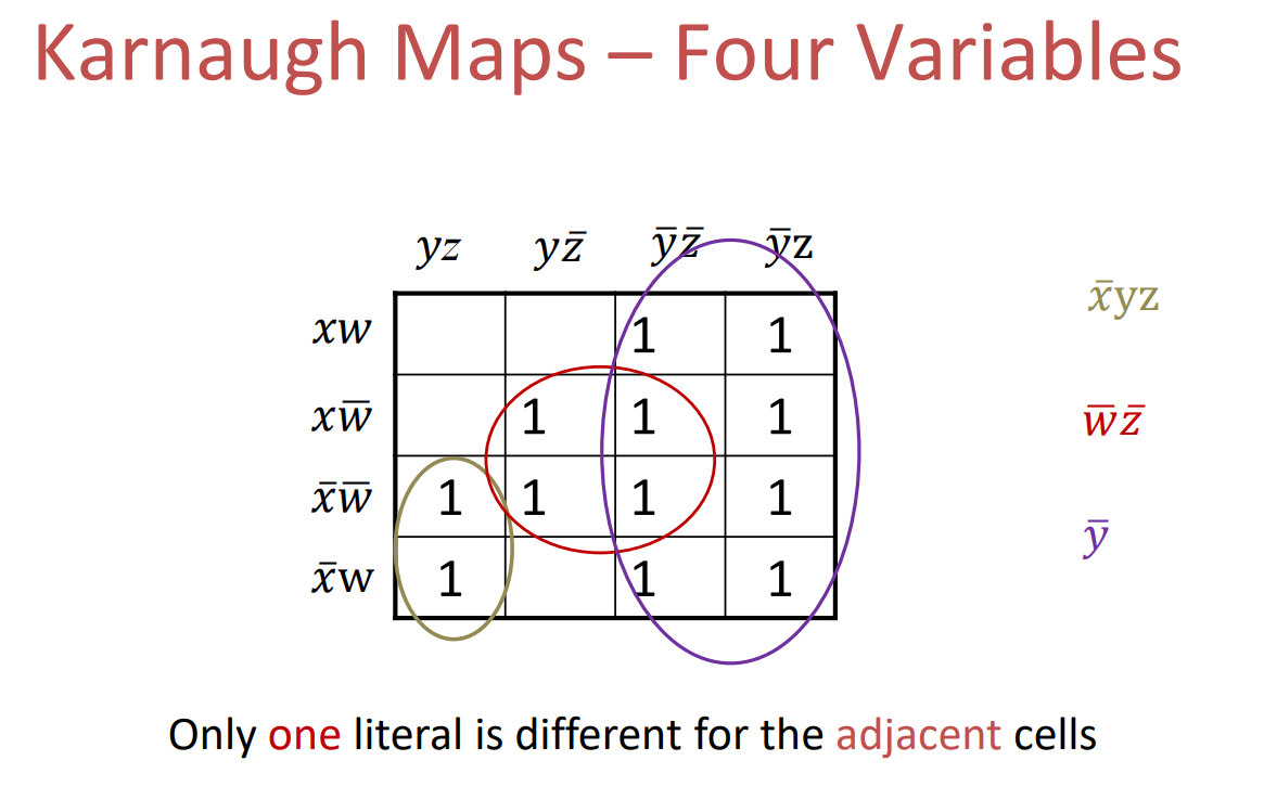
- Minimization of the Boolean functions if possible
- Design the logical circuits